
Kazoo Structure
|
Kazoologist Home What Is a Kazoo? History of the Kazoo Join AAK Kazoo Design, Construction, &Maintenance Pictures Links |
First Submarine Shaped Kazoo This is the diagram from the patent of the first submarine shaped kazoo, which was issued to George D. Smith, May 27, 1902. It included many inovative improvements to the kazoo. 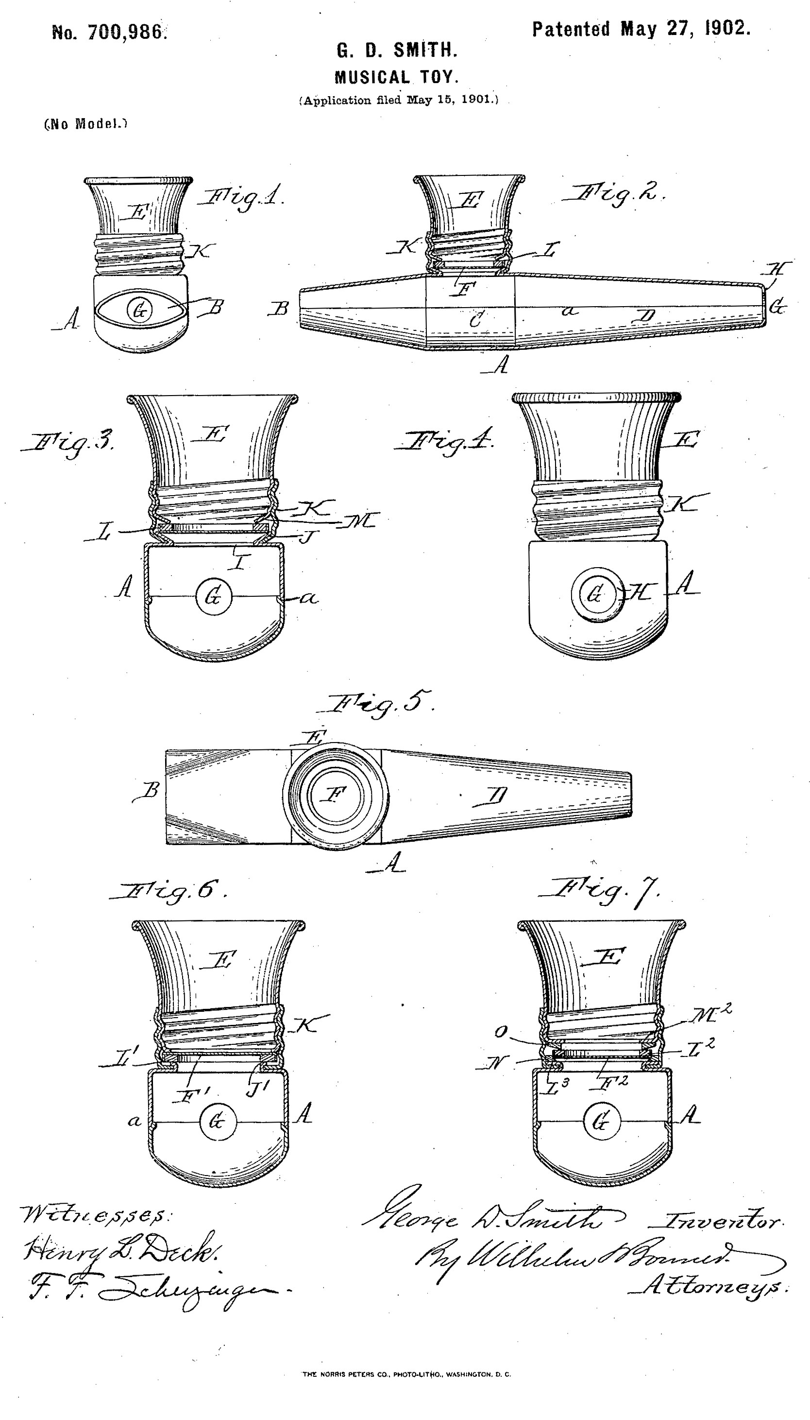 I don't know if any exactly like these were produced. Most of the modern ones simplify the design to varying degrees, frequently doing away with some of the important improvements. The
parts are connects by folding and crimping, rather than soldering.
This is the way the modern metal ones I have seen are put
together also.
The diagrams show three different variations on the method of holding the diaphragm Figs. 2 & 3, Fig.6, and Fig. 7. See also How a kazoo works--Smith's Submarine |
| Letter | Smith's nominclature | Purpose | Other names |
| A | Body | ||
| B | Mouthpiece | Eliptical shaped mouth piece, fits the mouth better than a round one. Diameter increases toward the air-reservoir. | |
| C | Air-Reservoir | Joins the two conical shapes of the front and back. | |
| D | Rear of instrument | Tapers toward the rear | |
| E | Trumpet | For confining and controlling external air-vibrations
produced by the diaphragm. Because it is threaded, it can be adjusted in and out varying the tension of the membrane to accomidate voices of different pitch and to compensate for the membrane absorbing moisture from the player's breath. |
lid, top, |
| F | Diaphragm | In Figures 2, 3 & 6 the diaphragm is on the bottom of the
ring L. In Figure7 the diaphragm is on top of the ring L |
membrane, resonator |
| G | Outlet opening | The necessary opening for some of the air to escape as the player's breath enters through the mouth piece. | |
| H | Flange | Annularly inward projecting flange. The end of the rear most end of the body, bends down thereby decreasing the size of the exist hole further. | |
| I | Hole | Hole in body that the sound comes through to vibrate the diaphragm. | |
| J | Flange | Being conical provides an inclined annular bearing-seat for the diaphragm holding ring. | |
| K | Threaded trumpet holding ring | Attached to the body, the diaphragm holding ring, is placed in it. The trumpet/funnel is screwed into the holding ring to keep the resonator in place and under the correct tension. | |
| L | Diaphragm holding annulas or ring | The diaphragm is glued to it to keep it at the proper tension. | cardboard ring, resonator ring, diaphragm ring |
| L3 | Flat Flange | The diaphragm holding ring sits here and is held by the trumpet threaded into the holding ring. | |
| M | Flange (Figures 2, 3 & 6 only) | Inwardly projectly inclined flange, which bears on the diaphragm ring | |
| N | Inside downwardly inclined edge washer (Figure 7 only) | Only the inner edge of the washer touches and holds the diaphragm ring. | |
| O | Outside upwardly inclined edge washer (Figure 7 only) | Only the inner edge of the washer touches and holds the diaphragm ring. |